UAV‑Based LiDAR and the Importance of Flight Trajectory
Jul 31, 2025
By Alex Knoll, CTO
Introduction
Unmanned‑aircraft (UAV) laser‑scanning systems combine a lidar sensor with a global navigation satellite system (GNSS) receiver and an inertial measurement unit (IMU). The lidar measures ranges to surrounding objects by timing the round‑trip of laser pulses, while the GNSS receiver and IMU record the position and orientation of the sensor. UAV‑mounted lidar is used to create detailed three‑dimensional point clouds for surveying, topographic mapping, forestry and infrastructure inspection. Precision in these applications hinges on the trajectory recorded by the GNSS/IMU. The trajectory file (often a smoothed best‑estimate of trajectory or SBET) provides the position and attitude information used to georeference every lidar point. Errors in this trajectory can lead to strip misalignment, warping of surfaces or systematic biases.
LiDAR accuracy depends heavily on the IMU’s precision. Over time, errors can accumulate in the accelerometers and gyroscopes that make up an IMU; calibrating the IMU corrects these errors and keeps the drone flying accurately. Rock Robotic therefore advise performing static and kinematic calibrations to converge the GNSS and IMU prior to capturing data and to minimize drift during the mission. The following white paper explains why the trajectory generation procedure—starting in an open area, collecting static GNSS/IMU data, controlled take‑off, high‑speed straight flight, figure‑8 pattern, mission flight and end‑of‑mission calibration—is critical for drone‑based lidar. Although the examples below reference Rock Robotic’s R3, R3 Pro and Rock Ultra lidar units, the principles apply to most survey‑grade UAV lidar systems.
Components of UAV‑Based LiDAR
| Component | Role |
|---|---|
| LiDAR scanner | Emits laser pulses and measures return time to calculate ranges. The Rock Ultra, for example, uses a 1550 nm laser and can collect about 1 million points/s with an effective range of 1000 m. |
| GNSS receiver | Provides high‑accuracy positioning; at least four satellites are required for a solution, and more satellites improve reliability. |
| IMU | Measures angular rates and accelerations. Errors in the IMU’s accelerometers and gyroscopes accumulate over time; calibrating the IMU corrects these errors and prevents drift. |
| Onboard computer | Records lidar pulses along with GNSS and IMU data, creates trajectory files and triggers cameras for colorization. |
Why Flight Trajectory Matters
Georeferencing and point accuracy
Each lidar pulse yields a range measurement relative to the sensor. To transform these ranges into Earth‑fixed coordinates, the position and orientation of the sensor at the exact time of each pulse must be known. The GNSS provides absolute position, while the IMU estimates roll, pitch and heading between GNSS updates. The final trajectory is typically computed using post‑processed kinematic GNSS and a Kalman filter that fuses GNSS and IMU measurements. If the trajectory is inaccurate (for example, due to IMU bias, poor satellite geometry or heading error), point clouds can exhibit strip offsets and warped surfaces.
Importance of setting up the base station in a Wide Open Area
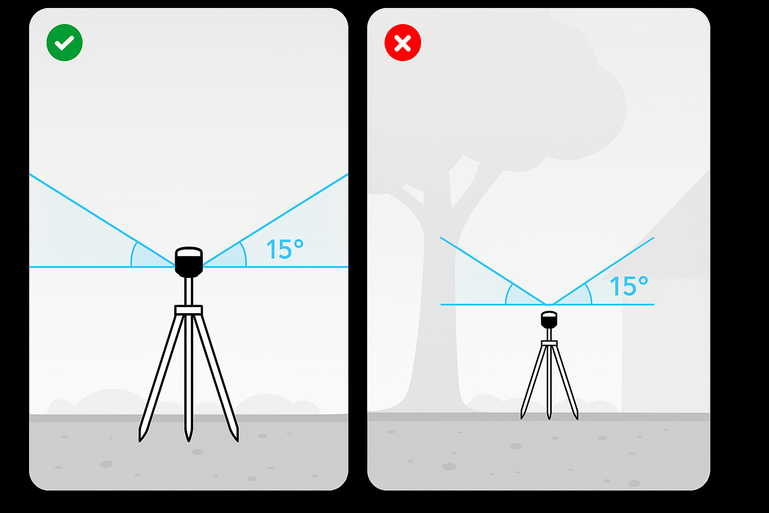
The reliability of GNSS corrections depends on where the base station is installed. A poor setup can introduce multipath errors—caused when GNSS signals bounce off nearby trees, buildings, or reflective surfaces before reaching the antenna. These reflections distort the timing of the signals and reduce positional accuracy.
To avoid multipath, best practice is to place the base station in a wide open area with clear visibility of the sky. Specifically, ensure there are no obstructions within 15 degrees of the horizon in all directions. Anything above that threshold—such as tall trees, structures, or vehicles—can cause reflected signals to interfere with the direct GNSS path.
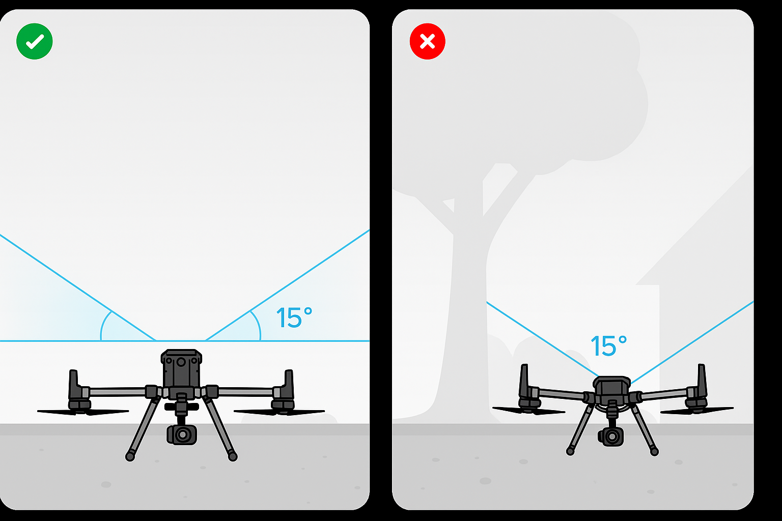
This principle applies not only to the base station but also to the UAV’s take-off and landing zones. If the drone powers on under tree cover or near buildings, the system may initialize with poor satellite geometry, leading to degraded trajectory accuracy throughout the mission. By starting both the base station and UAV in open sky conditions, you maximize satellite visibility, minimize multipath, and establish a stable foundation for centimeter-level lidar accuracy.
Importance of calibration
LiDAR accuracy depends on calibrating the IMU. When an IMU is not properly calibrated, its sensors can accumulate bias and noise that lead to orientation errors and drift. To mitigate these effects, lidar manufacturers prescribe specific dynamic maneuvers during the calibration flight. For example, Rock Robotic’s R3 Pro guides require a high‑speed straight line and a figure‑8 pattern to excite the IMU’s roll, pitch and yaw axes.
Step‑By‑Step Trajectory Procedure
The following sections explain the recommended flight procedure for Rock Robotic’s R3, R3 Pro and Rock Ultra lidar systems and why each step matters.
1. Start the drone in a wide open area
GNSS accuracy is sensitive to signal obstruction and multipath. Trimble’s RTK guidelines state that signal obstructions reduce the number of visible satellites and can cause multipath errors; they recommend locating the base station “in a clear environment with an open view of the sky” to minimize multipath. Starting a UAV in an open area applies the same principle: trees, buildings or metallic objects near the take‑off area can reflect GNSS signals and degrade the initial GNSS fix. When the lidar system is powered on, it begins logging GNSS and IMU data. A clear sky ensures that the system sees enough satellites (typically five or more) to compute a high‑quality position and velocity solution. Adequate GNSS lock is especially important for Rock’s long‑range Ultra system, which is capable of surveying hundreds of meters away; initial multipath biases can translate into centimeter‑level errors at those ranges.
2. Collect static GNSS/IMU data on the ground
Rock Robotic’s knowledge‑base instructs users to turn on the R2A/R360 lidar and start recording so the interface displays “Static Calibration”, then wait for five seconds until it indicates “Waiting for high velocity”. This static period allows the GNSS and IMU to converge. Similarly, the R3 Pro calibration guide advises users to power on the lidar, press the record button and “allow the system to record static data for a minimum of 30 seconds,” during which the lidar lights blink green. The stationary data helps estimate initial IMU biases and heading when the system is not moving. Without this initial alignment, errors accumulate rapidly during flight.
3. Controlled take‑off
A smooth, vertical takeoff avoids introducing ambiguous lateral acceleration, which could affect IMU alignment. Rock Robotic recommends avoiding lateral movement during ascent. Gaining altitude quickly and cleanly prepares the drone for calibration maneuvers.
4. High‑speed straight flight for heading alignment
Once airborne, the drone should fly straight at a speed greater than 5 m/s for at least 5 seconds. This maneuver—called “high-speed kinematic alignment”—provides linear acceleration that allows the Kalman filter to determine heading and the velocity vector. It helps establish the forward direction of the drone in relation to the LiDAR sensor. Without sufficient linear acceleration, heading errors may persist, causing the point cloud to be rotated relative to the true coordinate system. A straight line ensures that the forward velocity vector is well defined; rapid turns would confound the filter and produce poor heading estimates.
5. Figure‑8 pattern for kinematic calibration
After the straight‑line run, the pilot should perform at least one figure‑8 maneuver. Rock’s R2A/R360 guide states that the pilot should “fly at least 1 figure 8 pattern in the sky at a fixed altitude… at a speed of at least 5 m/s”, and the R3 Pro guide explains how to use both joysticks to create the loops. The figure‑8 pattern excites the IMU across its roll, pitch and yaw axes, thereby refining the sensor’s orientation. TxDOT’s mobile‑lidar manual requires crews to drive in a figure‑eight pattern to “excite the IMU” before data acquisition. By varying the vehicle’s direction and acceleration, the figure‑8 motion helps reduce covariances in the Kalman filter and lowers uncertainties in attitude and position. Inadequate excitation can result in increased drift and misalignment between flight lines.
6. Fly the mission
With the IMU calibrated, the pilot can proceed to fly the mission according to the survey plan. The mission typically involves flying a series of parallel lines (grid pattern) at a constant altitude and speed to achieve the desired point density. The Rock Ultra’s long‑range laser allows flights at 120 m AGL to cover larger areas and penetrate dense vegetation. Regardless of the sensor, maintaining a consistent speed and making smooth turns minimises abrupt accelerations that can disrupt the IMU.
7. End‑of‑mission high‑speed straight line
At the end of the mission, pilots should perform another high‑speed straight flight. Rock’s “Do you need to fly the calibration flight at the end of your mission?” article states that the final calibration involves flying a straight line back to the take‑off point at high speed (above 5 m/s) and avoiding rapid turns. This manuver recalibrates the IMU and ensures continuity between the mission trajectory and the static landing data. Skipping this step can lead to heading errors and misaligned strips. Performing the same calibration at the end of the flight is especially important when battery hot‑swaps have occurred; the article advises performing another high‑speed calibration after a hot swap to maintain data consistency.
8. Land and collect static data
After the final high‑speed line, the pilot should reduce speed and descend vertically. Rock’s end‑of‑mission guide tells pilots not to exceed 5 m/s during descent and to hover above the take‑off point before descending vertically. Once landed, the drone should remain static for at least 30 seconds to record stationary GNSS/IMU datalearn.rockrobotic.com. This final static session allows the processing software to refine the IMU biases and tie the end of the trajectory to a fixed position. The R3 Pro calibration guide similarly instructs users to record static data for 30–60 seconds after landing. TxDOT’s guidelines for mobile‑lidar systems emphasise that static sessions before and after data acquisition are mandatory.
Discussion and Implications
Accuracy benefits
Adhering to the full calibration sequence has measurable effects on data quality. Static sessions provide low‑variance observations that allow the Kalman filter to estimate biases in accelerometers and gyroscopes. High‑speed straight‑line runs yield strong observability of heading and velocity scale factors. Figure‑eight patterns excite the IMU in multiple axes, reducing correlation between errors. Calibration helps correct sensor errors and prevents drift; failing to perform these manuvers can lead to misaligned strips, inconsistent heading and poor absolute accuracy.
Applicability to R3, R3 Pro and Rock Ultra
Rock Robotic’s R3 and R3 Pro units use a similar lidar scanner and tactical‑grade IMU; the R3 Pro offers improved processing and may include additional camera options. The Rock Ultra uses a 1550 nm laser, achieves 1–2 cm post‑processed accuracy and can collect up to 1 million points per second with an effective range of 1000 m. Despite differences in range or laser wavelength, the fundamental requirement to accurately align the GNSS and IMU remains. Rock’s calibration guide emphasizes that turning on the lidar, recording static data, performing high‑speed and figure‑eight manuvers, flying the mission, and repeating the calibration at the end are critical steps for all their aerial systems. Thus the trajectory procedure described above should be followed when using the R3, R3 Pro or Rock Ultra.
Conclusion
UAV‑based lidar surveying relies on the accurate fusion of GNSS and IMU data to produce a precise trajectory. Calibration flights—starting in an open area, collecting static data, performing controlled take‑off, conducting high‑speed runs, flying figure‑eight patterns and repeating these manoeuvres at the end of the mission—provide the information needed to estimate IMU biases and heading. The Rock Robotic R3, R3 Pro and Rock Ultra systems incorporate tactical‑grade IMUs and long‑range lasers, but they still depend on the same calibration procedure to achieve centimetre‑level accuracy. Following the steps outlined in this white paper will help drone pilots produce reliable, survey‑grade point clouds and avoid costly re‑flights.